-
Posts
706 -
Joined
-
Last visited
-
Days Won
3
Content Type
Profiles
Blogs
Forums
Gallery
Pipeline Tools
3D Wiki
Plugin List
Store
Downloads
Everything posted by Vizn
-
Apparently, it is possible that your GPU is incompatible with the AE 3d engine: Solved: glb models in my composition view appears black/in... - Adobe Community - 14037517 If GPU is good... You should be able to import the GLB/GLTF back into C4D and see if the texture is actually there. If it is not, perhaps the exporter prefers texture files to be local or relative to the C4D file (use 'tex' folder). There are a few ways to convert to relative paths. Also, it seems that the GLB/GLTF format is an archive, like a zip, and AE is supposed to extract the textures upon import and create a new folder for the model and texture files in the AE project's folder location. (Import and add 3D models to your composition) If AE isn't creating the folder and extracting the texture, then it's possible the importer is bugged. While AE may prefer GLB formatting, it seems that they picked that format because it can include the textures making it easier to transmit to others, but if AE is just extracting the files, then in that case, there should be nothing to prevent you from creating the folder yourself and placing the exported model (GLB) and texture file there. BTW, FBX was a viable option for import to AE previously, but they may have changed that now (considering they removed 3d from Photoshop).
-
From your initial screenshot, I can see that you have World Axis active. Try turning that off.
-
Looking at the help info for the LOD object..some of the options seem counterintuitive. But then, I don't think the LOD object is meant to be used directly with deformers. The HR is still in the stack, so of course it will be deformed in real time as you adjust deformers along with LR. The deformers would need to somehow be excluded from LOD 0 while editing. Maybe some of the LOD options could help, but I don't have enough experience to say specifically how. Honestly, I don't think you can do this with LOD, which is primarily a camera distance display function.
-
Are you referring to the Level of Detail controls in the Project Settings? Example (from R21): It's the only way I can think of that you would still have the high-poly object as the target for the deformations. If you've manually created low-poly versions, wouldn't you just swap that in and the high-poly out of the deformer? Yet you say the high-poly is hidden, but still being deformed? It's not entirely clear what you've tried, or how you have things set up, so I am sorry if I have misunderstood the issue.
-
Not a lot of info to go on. Sounds like an issue with the conversion / export of the scanned object. 3D scanning may utilize voxel geometry in the process, and voxels do not hold UV info. So whatever the steps were to convert and/or export it to a mesh need to be looked at in terms of the options available. Or, there might be steps to the process missing prior to export.
-
Just selecting and splitting off sections and duplicating / moving them around. No care for intersecting. Tree canopies are very busy, so details like that are difficult to see, especially for clients who don't know what goes into making this stuff.
-
Ah, yes, that does sound handy for "growing" those things in an organic manner. I decided to go with a more purpose-built approach by making a few different trunk-like sweeps, then radial cloning them. Then I grabbed a canopy of leaves from an actual tree model and got busy shaping it. With textures and eventually hanging lanterns, I'm confident it will look good enough for a dimly lit interior. I appreciate the suggestions, all!
-
Beyond trying to make tree trunks from spline sweeps, I have no experience modeling realistic trees. Hoping to get some suggestions for modeling this interior decor tree. I see it as having a solid inner structural 'trunk' with the actual tree trunks mounted around it, which might help reduce the appearance of intersections (while modeling). I also don't see needing to be super accurate about how the canopy connects to the trunks, since there would be a bunch of flowers hiding quite a lot up there. I think I can handle the flowers. So any suggestions for how to tackle generating the trunks and branches?
-
Yep, "Visible Only" goes wonky sometimes. Seems to happen the more complex an object is. I prefer to use "Selected Only" and have never experienced it cut anything other than what is selected.
-
Yep, the LIne Cut and Plane Cut tools can get finicky. I'm still using R18 and sometimes it happens just like you describe. I have adopted a couple of moves to quickly address it and keep moving. First is the shortcut M,M for the Connect function, which will create an edge between 2 opposing points, or edges. So when the cut tools won't cut the face, I select 2 opposing edges, M,M to connect them, then I can select points and weld as needed. Second is the Create Point tool (shortcut M,A). Activate it in edge mode and you can click to add points to any edge. Then Connect points, or weld, or whatever you need.
-
Interesting topic. I keep all of my libraries on a dual-HDD NAS. Two 6GB Drives are in a RAID so they mirror each other for data protection. I have dozens of CG Axis libraries, plus dozens of Evermotion. CG Axis is the best all-round, IMO, especially because they give you C4D + VRay along with MAX + VRay. Anyway, I really only wanted to post about HOW I interact with these libraries. I recommend that you DO NOT UNZIP the whole model archive. It takes too much space to extract AND maintain all of the files. I do extract all of the textures to a folder in the same dir as the archive. This is for easy re-linking. So, I keep the collection archives organized into appropriate named folders for clarity. I also put all of the PDF preview files into a separate directory, which is where I go to first look for a model visually. When I pick a model from the PDF, I open the archive and extract only the file I need. Open it and re-link textures, then save it (outside of the archive) for future use. This method allows to keep the bulk of the collection in an archive, only grabbing then saving what I need after setting it up for my pipeline. Ultimately, this saves space on the NAS, and has the added benefit of keeping the original in pure original form, while having an updated version for my needs. While this helps me conserve space in the present, it doesn't really address keeping backups of such huge amount of data. My only hope is that both drives don't die at the same time!
-

3D models in seconds not hours or months with the Omnia Generative AI Tool
Vizn replied to MJV's topic in Discussions
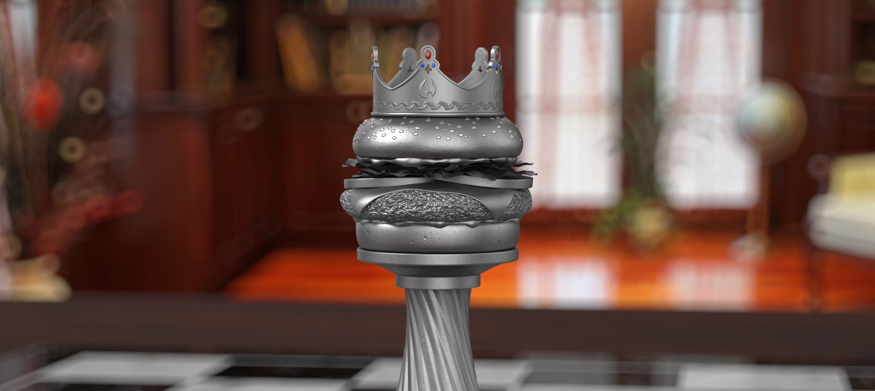
Make hamburger? Make couch?! FREE??? I'm cancelling my subs! -
Some materials are still a struggle to replicate. BTW, I am using VRay 3.6 For instance, take a look at the main material for this pendant light: Vikkarlight - Melt Pendant (Red) It has a different look when off or on. I really only need the look when it is on, within a dim setting. My approach to materials has mostly been "cheat it as much as possible, as long as it looks fairly close in the render". Not sure how to cheat this one. I tried 2-Sided materials, but results weren't even close. The struggle is refraction on the outside, with these crazy interior reflections. Maybe it's not refraction, but instead some kind of molded plastic with mirror tint? 🤔🤷♂️ At the moment I am using an image clipped from the website, applied in flat projection on the model, with a "look at camera" effect. Taking this further, I will make 3 versions of the image, so it looks more random. But it works. WIP:
-
The current responses seem to be going into more detail than you need, at the moment. So, from this picture I can tell that you are using Cubic projection. All you need to do is rotate the projection gizmo. To see the gizmo, you need to activate Texture Mode and utilize Enable Axis function. You will see yellow grids in the shape of the projection you choose. Use the rotate function to adjust the projection so it aligns along that side as you wish. Should just be a single 90 degree turn on one axis to get this to align.
-
Along with the other suggestions, you could also try the handy 'untriangulate' mesh command. Shortcut = U~U, or U~Shift+U for its settings.
-
First, you have too many lights. Look up "three-point lighting" and / or product photography studio setups for some foundational knowledge. Second, your lights appear way too big, so no matter what intensity you set, the product is getting flooded with light. Once you get a three-point setup, positioning them will also be key to getting the overall look. Study up! 🙂 Flat metallic printing will still look mostly flat when the main light source is straight on. Consider giving the box a very slight rotation, so the front is a bit more towards the cups.
-
It's for static conceptual interior renders and won't be close to the camera. Good idea about enlarging the texture resolution. For the bindings, I made some cuts with the applied texture as a guide and converted them to splines. Did a circle sweep with fillet caps, added displacer noise (as you suggested), then adjusted the UVs to match. Not too bad for what I need. Just need to flip a duplicate to the other side, connect/weld, give them some thickness and lighting hardware to finish it up, me thinks. The scene is filled with lots of other custom pendants, plants, furniture, etc so I'm confident it will blend in nicely.
-
Thanks for the detailed suggestion @HappyPolygon. I am not really familiar with Hair or edge flow re-topology. I fear it would take too much time for me. I was able to cut the swoosh shape out of the bell and flat map the original image to it. Just have to create some 'vertical' strands. I know it's not really the level of detail some 3d mavericks here would go with. The swoosh cut is a bit off, so I might redo it. Progress:
-
Hi, how are you? I have this interesting pendant to model. It is 30 in. D x 24 in. H My initial idea was to somehow use a loft to generate the organic shape of the main woven bits. However, I am not sure how I would generate the lofting splines, so it doesn't seem like a good approach and I don't want to spend too much time on it. Looking for suggestions how I might model this efficiently. I am using R18.
-
I'm old enough now that my eyes naturally anti-alias everything! 🙃
-
As far as the texture paths go: Are the textures pulled into the 'save with assets' location? (there should be a 'tex' folder in the same location with the new collected file.) If yes, open the 'saved with assets' scene file. Use the Texture Manager and the "Localize" function to fix the texture file paths.
-

Rendering a voronoi fracture object in the camera tracker
Vizn replied to Keith Vick's topic in Cinema 4D
In the object list, the 'traffic lights' control: top one indicates seen in viewport or not, bottom one indicates will be included during render or not. Further, the little green check is like off and on for generators, deformers, lights, etc Quick Tip: holding Alt key allows to affect both traffic lights at the same time.

